This article is actually an excerpt from Wladston Ferreira Filho‘s new book Computer Science Unleashed. This book is about all the groundbreaking technologies behind the World Wide Web. We might even take them for granted these days, but there are important and learnable technologies behind how it all works. Read on and marvel at the engineering ingenuity that enables simple physical links between computers to become a global, near-instant communication medium that everyone can use almost for free.
Humans crave connections, and the advent of the digital revolution has empowered us to be more connected than ever before. The Internet has unleashed upon billions of people unprecedented economic and political freedom, as well as powerful means of control and domination. Yet, the vast majority of us are oblivious to its inner workings.
Skilled people who can program computers to use the Internet are at the vanguard of the digital revolution. This chapter will teach you how the Internet works, so you can join this select group. You’ll learn to:
- Link computers to one another to make a network,
- Combine networks using the Internet Protocol,
-

Locate a recipient from its Internet address,
- Find a route through the Internet to that location,
- Transport data between distant applications.
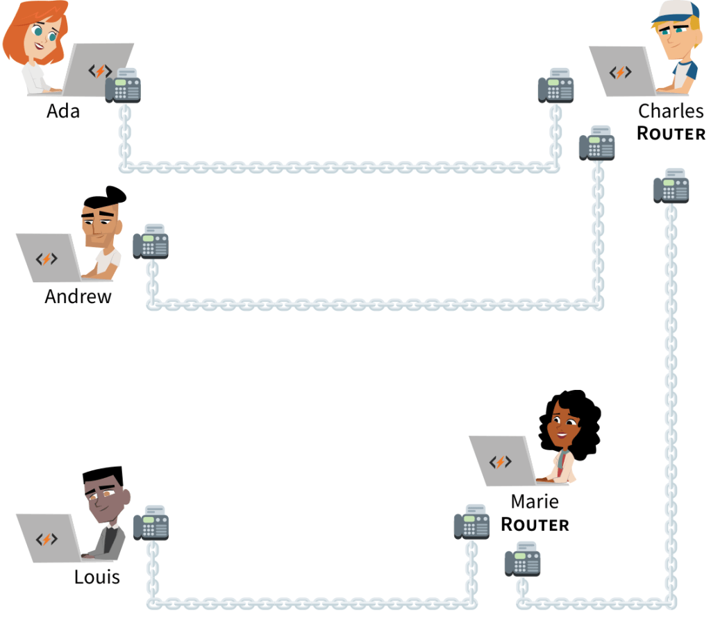
Before the Internet, telecommunication between two parties required a direct physical link. In the 1950s, each telephone had a wire leading directly to a central station. For a call to go through, an operator had to physically connect the wires of two telephones. For long distance calls, wires were laid out between distant stations, and several operators in different places had to physically connect the chain of wires linking the two phones.
The Internet did away with this. Wires aren’t physically reconfigured to create direct, exclusive links. Instead, the information is retransmitted step by step via a chain of linked devices until it reaches its destination. This eliminates the need for wire operators and central coordination. Also, wires are no longer constrained to serve a single connection–many concurrent connections can share the same wire. This allows global communications to be instant, cheap and accessible.
However, modern networking technology is more intricate than early telephony. It has many successive layers, each building on top of the previous. Let’s explore how connections are made at these different levels, starting with the most basic layer.
1.1 Links
Table of Contents
A direct connection between two computers is achieved through a transmission medium: a physical channel where signals flow. It can be a copper wire carrying electric currents, a fiber-optic cable directing light, or air hosting radio waves. Each connected computer has a network interface to send and receive signals in the transmission medium. For instance, cellphones have a radio chip and antenna to handle radio signals traveling through the air.
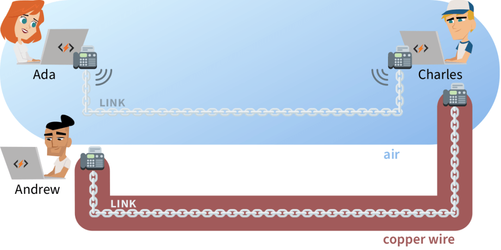
In order to communicate, network interfaces must agree on the rules to follow when sending and receiving signals. This set of rules is called the link layer.
When a medium exclusively connects two computers, we say they maintain a point-to-point connection, and their link layer relies on the most basic set of rules: the Point-to-Point-Protocol (PPP). It merely ensures the two computers can identify each other and exchange data accurately.
However, connected computers don’t always get to enjoy such an exclusive link. Often, they must share the transmission medium with several other computers.
One way to link computers in an office is to plug each of them into a hub with a wire. The hub physically connects all the wires that reach it, so a signal sent by one computer will be detected by all the others! This will also happen on your home WiFi, since the same radio frequency is used by all connected devices. Communications can become messy if all of them use the medium at the same time.
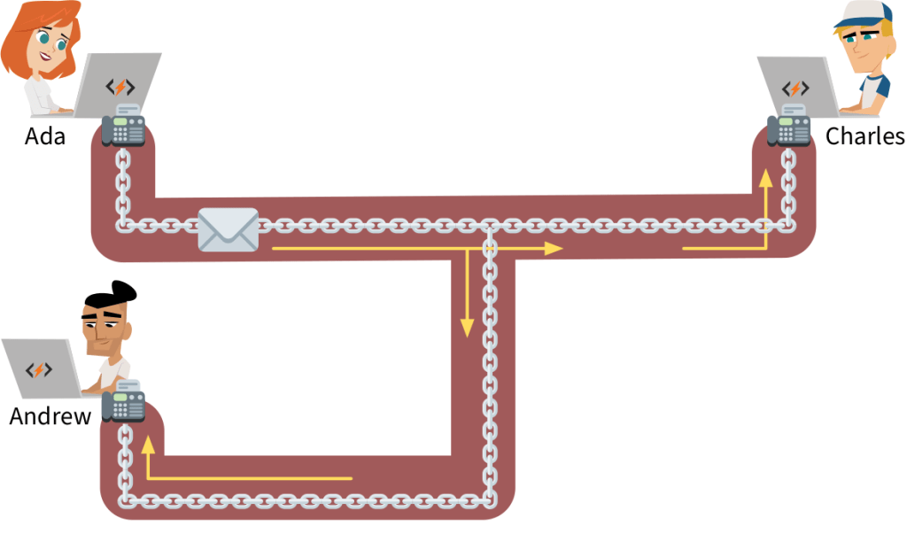
The link layer contains a set of rules to define how computers should share their communication medium, fittingly called Medium Access Control (MAC). The rules resolve two main challenges:
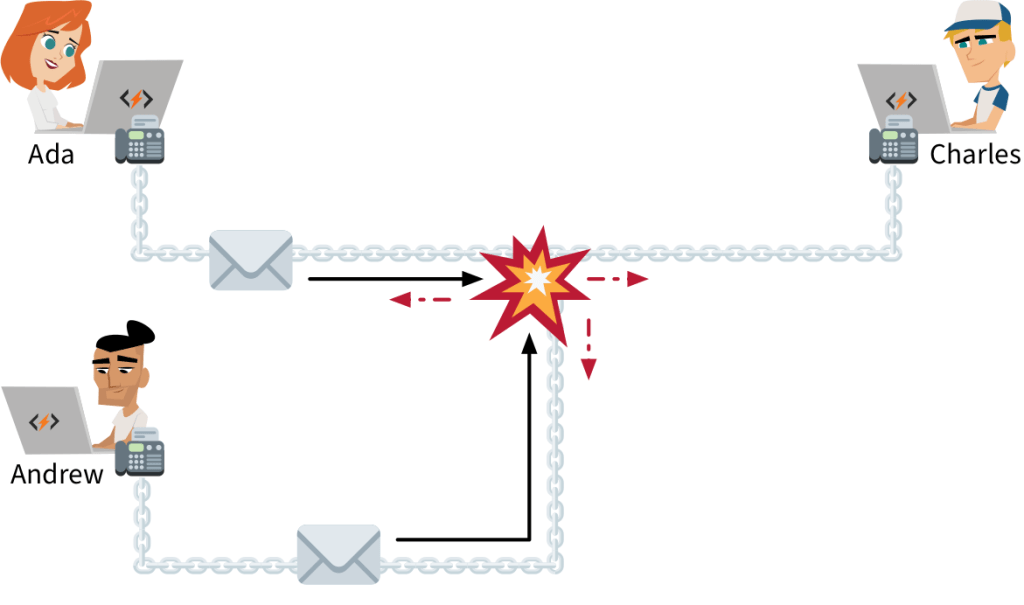
COLLISIONS — If two computers send a signal through the same medium at the same time, the resulting interference garbles both transmissions. Such events are called Collisions. A similar problem occurs when your group of friends or family talk over each other hand no single voice can be clearly heard.
There are methods to avoid collisions. First, only start transmitting signals when no other computer is transmitting. Second, monitor your communications–if a collision occurs, wait for a brief but random amount of time before trying to transmit again.
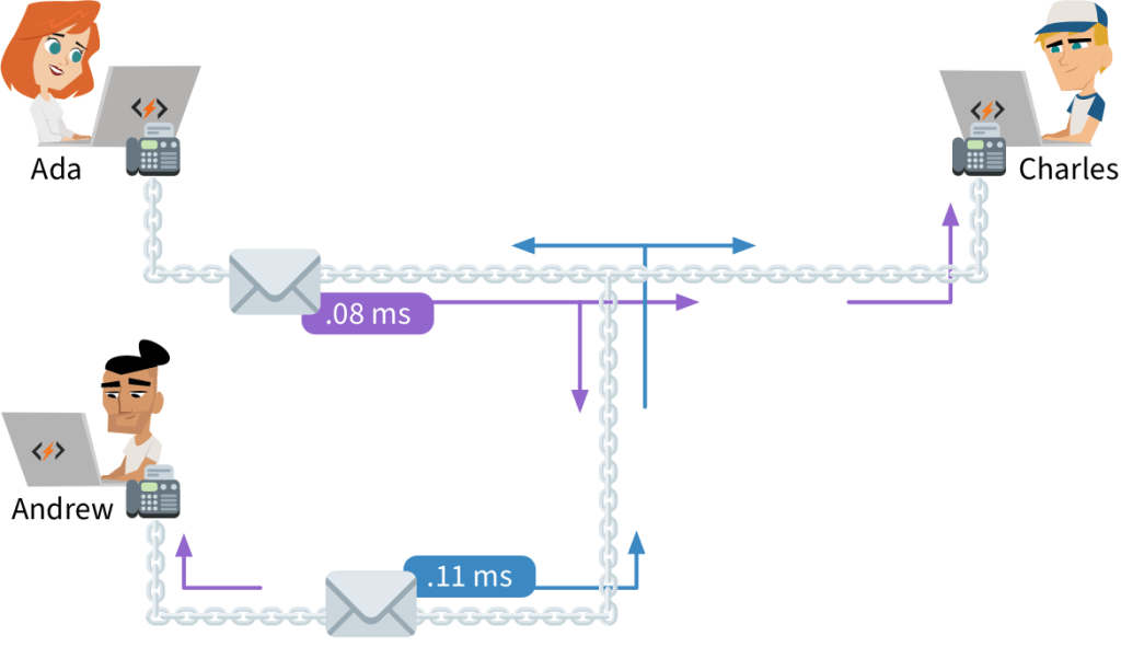
These methods have some limitations. If there are too many transmission attempts through a medium, collisions will occur relentlessly. We say the link is saturated when excessive collisions break down communications. Have you ever been frustrated at a large venue because your phone wouldn’t send text messages or make calls? This may happen if too many phones are attempting to communicate concurrently and the cellular link becomes saturated.
PHYSICAL ADDRESSING — Ada and Charles have a direct link between their computers. Ada wants to talk with Charles, so she transmits a signal with her message through the medium. However, the medium is shared, so everyone linked to the medium gets the message. How can the other computers know that the signal they picked up was not destined for them?
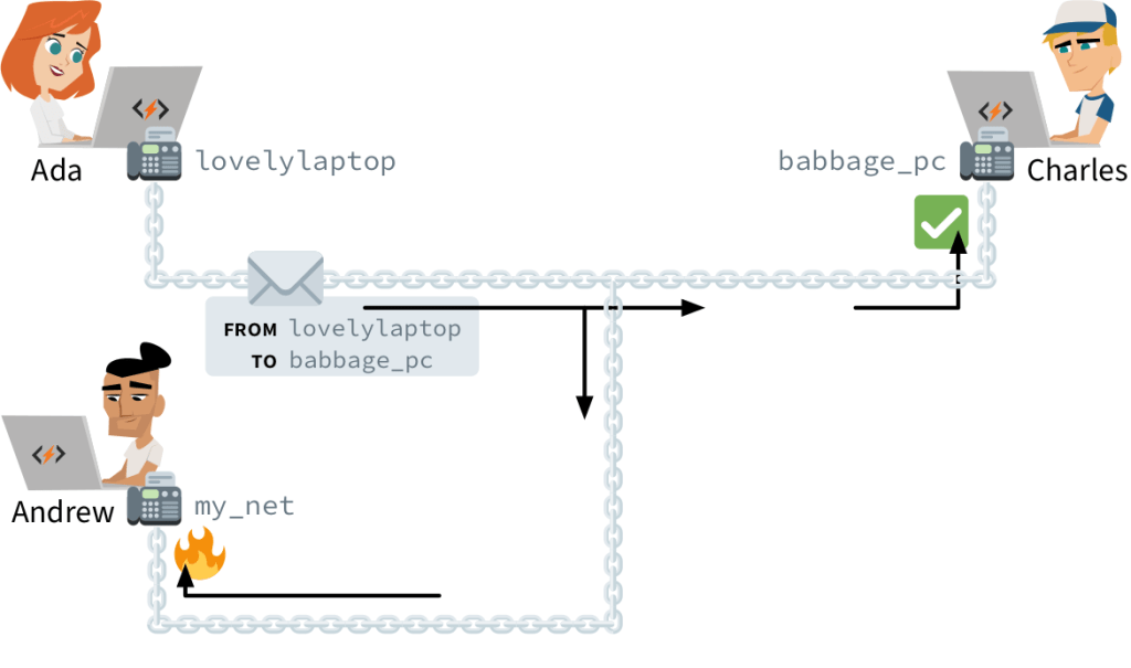
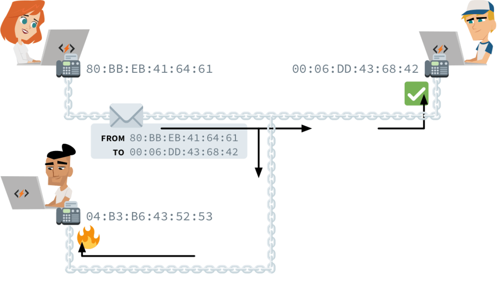
Each computer’s network interface has an identifier, known as its physical address or hardware address. A transmission in a shared medium must begin with two such addresses: that of the recipient and that of the sender. Upon receiving a transmission, a computer will know if it should be ignored or picked up and to which address it should reply.
This can only work if physical addresses are unique: if two computers use “my_netinterface”, we’re back to square one. For this reason, virtually all network interfaces follow a naming scheme defined in the rules of Medium Access Control. These standard physical addresses are called MAC addresses.
MAC Addressing
Computers, smartphones, smart watches, and smart televisions can each have WiFi, Bluetooth, and Ethernet network interfaces. Each network interface has its own, unique MAC address marked into the hardware during production. You should not worry about assigning a MAC address to your computer: you can always use the one that came with its network interface.
Since MAC addresses are simply large random-looking numbers, network interface manufacturers around the world must coordinate to avoid accidentally assigning the same number to two different devices. To this end, they rely on the Institute of Electrical and Electronics Engineers (IEEE), that assigns each of them a different range of MAC addresses.
A MAC address is expressed as six pairs of hexadecimals1 separated by colons. The first half of the address is an identifier assigned by the IEEE to a unique manufacturer. This manufacturer then chooses a unique second half for each network interface.
60:8B:0E:C0:62:DEHere, 608B0E is the manufacturer number. This specific number was assigned by IEEE to Apple, so this MAC address should belong to an Apple device.2 A device’s MAC address is often written on a label stuck to the packaging or on the device itself, next to the serial number.
There’s a special address reserved for transmissions to all computers in a medium. It’s called the broadcast address, and it reads FF:FF:FF:FF:FF. You use it when you try to connect to an unknown device. For instance, when your smartphone’s WiFi card isn’t deactivated, it persistently broadcasts to FF:FF:FF:FF:FF that it’s looking for an access point. Discoverable access points will respond with their own MAC address so you can establish a link.
Such discovery broadcasts, like all other transmissions, contain the sender’s MAC address. Walking around with a smartphone can therefore be like walking around with a loudspeaker shouting your name non-stop, only using radio waves instead of sound and the MAC address instead of your moniker. In 2013, Edward Snowden revealed that the NSA3 monitored the movements of people by sniffing WiFi transmissions in big cities, storing records of where each MAC address was seen.
You can also set your own network interface to promiscuous mode, and it will pick up all transmissions regardless of their intended recipient. Doing so allows you to discover hidden WiFi networks, to list which MAC addresses are in your area, and sometimes even to read the contents of other people’s transmissions. Browsing the Internet through an unsecured WiFi network can therefore be unsafe: your communication is broadcast for anyone in range to hear. This is why encryption4 is important for WiFi’s link layer.
Be careful: a network interface can be configured for its transmissions to start with any MAC address for both the recipient and the sender. Nothing stops a malicious agent from impersonating you by using your MAC address in their transmissions. This type of attack is known as MAC spoofing. When the link layer was invented, security wasn’t a concern. Protocols are evolving to become more secure and neutralize such attacks, but it’s an ongoing process.
Frames
Sometimes, a transmission must contain a lot of data, and sending out a single, big fat message is impractical. Network interfaces and computers are not all capable of the same transmission speeds. Moreover, what would happen if a collision occurred in the middle of the transmission? The entire transmission would have to be discarded, as it would be difficult for the sender and receiver to determine exactly which parts of the message were received and which were not.
To solve these issues, long messages are always split into small parts, each sent as an independent transmission. The duration between transmissions can vary according to the capabilities of both computers: slower devices needs longer breaks. If an error occurs, it is only necessary to discard and resend the small transmission that failed.
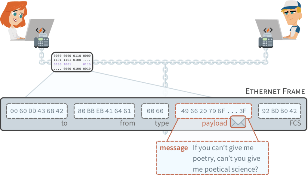
Each independent transmission is called a frame. Standard WiFi protocols cap the size of frames to 2,346 bytes. Thirty-four bytes are needed for MAC addresses and error-detecting codes. Therefore, a WiFi frame can ultimately carry up to 2,312 bytes of data, called the payload.5 In wired networks, the maximum frame size is usually 1,526 bytes, with room for a 1,500 byte payload.
On rare occasions, disturbances in the medium interfere with a transmission, and the receiver picks up signals that don’t encode exactly the same information that the sender intended to transmit. Let’s see the special field that was added to address this problem.
FCS — The last part of the frame is the FCS (Frame Check Sequence), and it ensures that information was transmitted accurately. It doesn’t add new information to the transmission: it is merely the result of a calculation using the contents of all other fields. Changing any content before the FCS should cause the FCS number to change as well.
Upon receiving a frame, a computer calculates the expected FCS number from the information it received and compares it to the received FCS. If they don’t match, the frame is discarded. If they match, we know that the message wasn’t garbled and trust that the received payload is error-free.
TYPE — The frame shown in Figure 1.7 has one last field we haven’t talked about: the payload type. It tells the receiver which rules should be followed to interpret the data in the frame’s payload. In the next section, we’ll explore the most common set of such rules.
1.2 Internet
We’ve seen that the link layer enables directly connected computers to exchange messages inside frames. The internet layer, also known as the network layer, specifies how to transmit these messages between computers that are not directly connected.
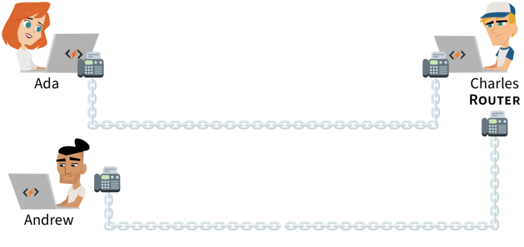
The trick is to equip some computers, called routers, with multiple network interfaces. All computers in a network are then linked to at least one router, and all routers are linked to at least one other router. When a router receives a message at one of its network interfaces, it can forward it to another router through a different network interface.
LOCAL AREA NETWORKS — We can ask a router we’re linked with to forward a message to a computer we’re not linked with. Suppose you have a wired network in your home connecting a router and a desktop computer. Suppose the router is also directly connected to a smartphone in a different, wireless network.
Even though the desktop computer and the smartphone are not directly connected to the same network, they can send messages to each other using the router as a relay. Computers from different networks in close vicinity that can talk to each other through routers form a larger network, called a Local Area Network (LAN).
In a home or small office, one router will be enough to link all the computer networks in the area. When assembling a LAN that covers a large organization such as a university or hospital, many routers may be required to link all the different computers networks into a fully connected system.
WIDE AREA NETWORKS — But why stop there? If your router is linked with a router outside your home, which in turn is linked with a router at the university, you can ask for your message to be forwarded to computers on the university’s LAN. When distant LANs are connected to each other, they form a Wide Area Network (WAN).
A WAN can grow larger as more LANs are connected to it. Different WANs can also be connected to form an even larger WAN. The largest WAN in the world is a collection of thousands of interconnected networks that we call the Internet. It’s the network we use every day to send emails and browse the web. In 2019, this WAN contained over a billion computers. Let’s see how they all got connected.
Interconnection
The most straightforward way to connect your router to the Internet is to pay for it. Some organizations on the Internet will link one of their routers to yours, and allow messages to and from your network to pass through their network via this link. This paid service is called transit, as all of your messages will transit through their network before going to the specific router you’re aiming for.
However, transiting through a third party network is not always necessary in order to connect to another router of the Internet. If, for example, two nearby universities communicate a lot, they can link their routers in order for messages to flow directly between their networks. This can save money, as these messages would otherwise have to transit through a paid connection. The free exchange of messages between the networks of different organizations is called peering.
Routing
Any computer linked to a router of the Internet can ask for its messages to be forwarded by other routers. Messages can be routed over large distances. For instance, there is a system of submarine cables linking routers in many coastal cities:
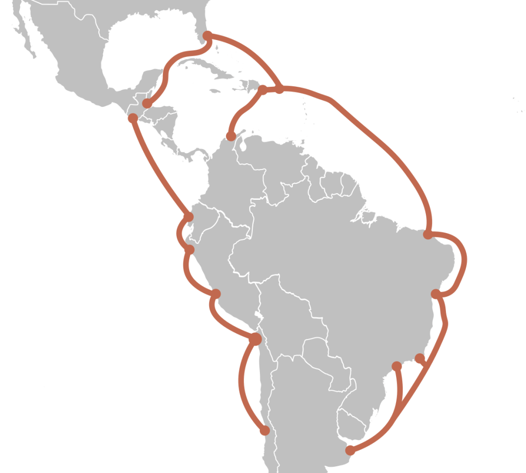
There is no direct link between the routers in Miami and Buenos Aires. However, Miami is linked with Puerto Rico, which is linked with Fortaleza, which is linked with Rio de Janeiro, which is linked with Buenos Aires. Miami and Buenos Aires can exchange messages through these cables if routers along the way forward the messages back and forth. Today, there are submarine cables linking hundreds of coastal city routers around the globe:
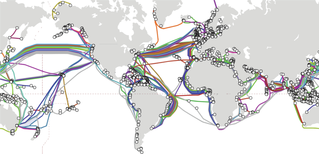
Virtually every other city on Earth is directly or indirectly linked to these coastal cities, often through cables in the ground. Communication satellites also have routers to establish wireless links to remote locations. All routers can forward messages, so a message you send on the Internet can be routed to any other computer on the Internet. That is, if a path to it can be found.
Location Addressing
In the link layer, computers are identified by a physical address. Physical addresses uniquely identify computers, but they don’t give any hints on where a computer is connected and how it can be reached. If the computer moves to the other side of the world, it will retain its physical address!
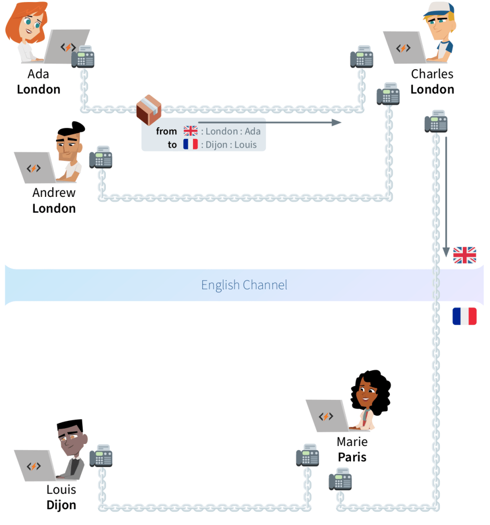
Suppose you mailed a package to Louis through the post along with a picture of him instead of his address. This package has a defined destination; however, an international postal service would have no way of knowing which direction the package should be sent in order to deliver it to Louis.
Post offices must first know to which country the package should go. The first post office in that country should then know to which province or state it should go. The next post office should know the city, and the final post office, the street address. An address containing all this information is called a hierarchical address. As with post offices, routers need a hierarchical address of the package recipient’s location:
For this mechanism to work on a global scale, all computers involved must follow the same set of rules to create and handle package forwarding requests. A computer in China must understand a request from a computer in Nigeria, even though the two may use different languages, operating systems and hardware.
Internet Protocol
We’ve seen a computer must follow the rules of Medium Access Control to establish a link with another computer. Similarly, it must follow the Internet Protocol, or IP,6 to ask routers to forward messages to other computers on your LAN or on the Internet.
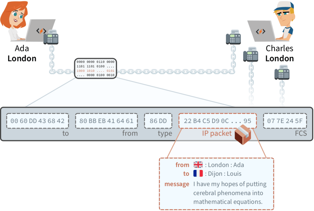
A message forwarding request that follows the IP rules is called an IP packet. The IP packet is essentially a big number, where digits in specific positions encode key information. Virtually all computers understand IP packets and are able to forward them. This makes an IP packet easily movable from one computer to the next, until it reaches its destination.
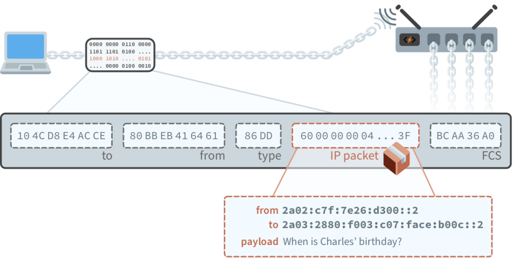
An IP packet contains the location addresses of its sender and recipient, followed by whatever data they want. To send an IP packet, we transmit a frame where the payload is the IP packet, and the frame type is 86DD. When a router receives a frame of this type, the IP packet is re-transmitted in another frame to the next computer in the path of the packet’s destination.
In order for IP packets to be forwarded around universally, everybody must agree on a standard for location addressing. We’ve seen how physical addresses are allocated by manufacturers according to the rules of Medium Access Control. Let’s now learn how the Internet Protocol does this for location addresses. We will then see how the Internet Protocol defines routing rules based on these addresses.
1.3 IP Addressing
The Internet Protocol sets the rules on how location addresses work–that’s why they’re called IP addresses. Computers can only send or receive IP packets after they get an IP address. Permission to use a group of IP addresses is first granted to an organization. These addresses are then assigned to computers which are directly or indirectly associated with the organization.
In order to explain how this process works, let’s define what IP addresses are and how they’re written.7 An IP address is a number 128 bits long.8 They’re typically written in hex, with colons separating eight groups of four digits. This is Facebook server’s IP address:
2a03:2880:f003:0c07:face:b00c:0000:0002IP addresses can be shortened by omitting the leading zeros of any four-digit block:
2a03:2880:f003:c07:face:b00c::2As with a postal address with country, city and street, IP addresses are hierarchical for routing to be possible. While the broadest part of a postal address is the country, the broadest part of an IP address is the routing prefix (2a03:2880).
The prefix shows up as the first digits of an IP address. Once an organization is granted such a prefix, it has the right to assign any IP address that begins with that prefix to its computers. The prefix has a variable length: organizations that have more computers to manage are granted shorter prefixes. Some organizations are even granted multiple prefixes.
For example, we know that all addresses that begin with 2a03:2880 are assigned to computers inside Facebook’s network. Those that begin with 2c0f:fb50:4002 are in Google’s network in Kenya. For its data center in Singapore, Google was granted the prefix 2404:6800.
For routing purposes, the LANs and WANs that share the same prefix are organized in small networks called subnets. The digits after the routing prefix and up to the middle of an IP address indicate in which subnet (f003:c07) a computer can be found.
2a03:2880:f003:c07:face:b00c::2This means there’s a network at Facebook where all computers have IP addresses that begin with 2a03:2880:f003:c07. Together, the routing prefix and the subnet form the network ID (2a03:2880:f003:c07) of an IP address. The network ID is always 16 digits long (including omitted zeros). This means an organization with a longer routing prefix can have less subnets within it.
Finally, the next 16 digits of an IP address are called the interface ID (face:b00c::2), as they identify a specific network interface within a subnet. Many network administrators simply fill in this part of the IP address with the device’s MAC address. These digits can be any number, as long as it’s only used once per subnet.
For this addressing system to work universally, there must be a mechanism to ensure no two organizations use the same routing prefix. As was the case for MAC addresses, engineers solved this through some international coordination.

IANA
Engineers worldwide agreed that an American non-profit organization, the Internet Assigned Numbers Authority (IANA), decides who gets control over which IP routing prefixes. In practice, IANA delegates most of its power to five non-profit organizations called Regional Internet Registries, or RIRs. To do so, it allocates each RIR short hex combinations that they can use as the first digits of the routing prefixes they assign.
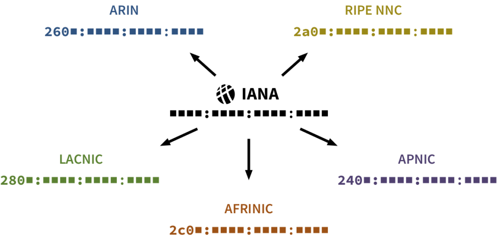
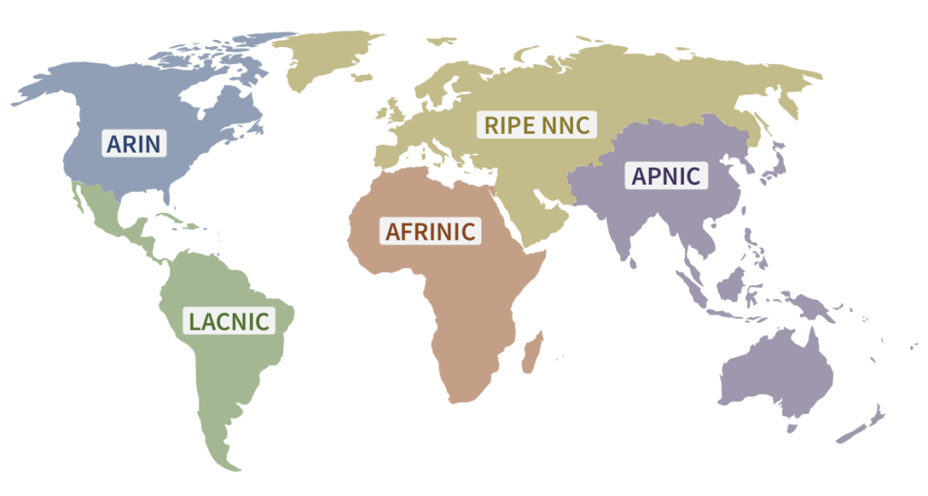
To obtain a routing prefix for your organization, you must make a request to the RIR of the region where your routers will be. That RIR will then assign you a prefix starting with one of their combinations of hex digits that IANA allocated them.
For example, Facebook, which has headquarters in Ireland, was granted its routing prefix by RIPE NCC. Likewise, the Swiss bank Credit Suisse has a Latin American branch that was granted a routing prefix by LACNIC:
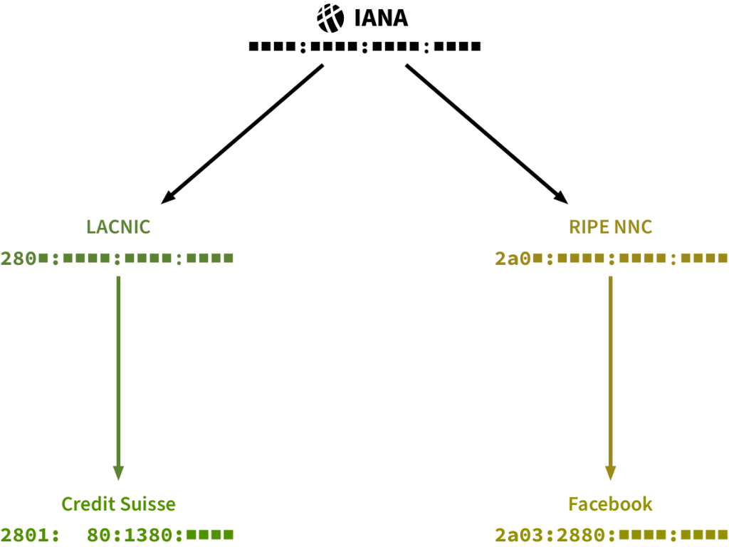
This means computers in the Latin American Credit Suisse branches may be assigned IP addresses as follows:
2801:80:1380: ■ ■ ■ ■ :____:____:____:____Network administrators in the bank will assign a unique combination of hex digits to each of their subnets such that they fit in the remaining space of the network part 

. Since each hex digit can have 16 different values, the bank has enough space for 164 = 65,536 different subnets. Facebook, being a larger organization, was granted a prefix with room for over 4 billion subnets!
We’ve seen that network administrators can choose how the sixteen blanks of the interface ID are to be filled for individual devices. Such devices may then send and receive IP packets to and from the Internet as long as their router has connectivity.
Internet Service Providers
Most individuals and small organizations don’t deal directly with RIRs, nor do they maintain peering links to other computer networks. Instead, they buy Internet connectivity from specialized companies, which are called Internet Service Providers (ISP). ISPs install routers close to their customers. That way, they can easily link one of their routers to a router in any customer’s premises. They also allocate a routing prefix for each of their customers.
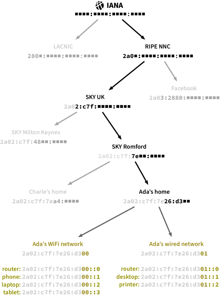
Let’s see how it works in practice. In the United Kingdom, an ISP called Sky was granted the routing prefix 2a02:0c7f. Sky operates in many British cities, so the prefix is divided between their regional bases. For instance, they assign 2a02:c7f:48 to their Milton Keynes network and 2a02:c7f:7e to the one in Romford.9
Let’s suppose Ada lives in Romford and wants to set up a network in her home. She has a desktop computer and a printer which she wants to connect using an Ethernet wire. She also wants her own WiFi network to connect her smartphone, tablet and laptop.
Ada hires Sky, and they link their Romford router to a router in her home. Sky assigns Ada’s router a 14-digit routing prefix based on the one of their Romford base. Each network in Ada’s home (wired and wireless) gets assigned a subnet, based on the routing prefix Sky allocated to Ada. Figure 1.19 on the next page shows the full IP address allocation path from IANA to each of Ada’s devices.
Ada’s router receives IP packets from several different computers, yet it’s easy for her router to decide on which link to forward each packet it receives. Packets addressed to a computer in one of Ada’s subnets can be directly delivered. All other IP packets it receives are forwarded through the link to the ISP.
For routers that don’t rely on an ISP, it’s not so easy: they obtain connectivity from links with several routers from multiple computer networks. But how do they decide on which link they should forward an IP packet? And how can they be sure that they are forwarding it to a router closer to their final destination?
1.4 IP Routing
Suppose Ada wants to send a message to Facebook from her laptop. She will use the Internet Protocol, so she starts by crafting an IP packet that includes her own IP address, Facebook’s IP address, and her message as the payload. She then transmits the packet in a WiFi frame from her laptop to her home router:
Several routers, starting with the one at Ada’s home, retransmit the packet until it reaches Facebook. Along the way, each of those routers must choose in which direction the packet should “hop” to reach the next router. The last router will then make the packet “hop” towards its final destination computer.
Tables of Addresses
Routers choose the next hop of a packet based on its destination IP address. In order to do so, they are equipped with a table filled with addresses. Rows list possible IP addresses the router is configured to recognize. For each address, the table indicates which computer should be the next hop of a packet destined to that address. Every router has a unique table that reflects how the router is linked. For example, here is how Ada’s router is linked:
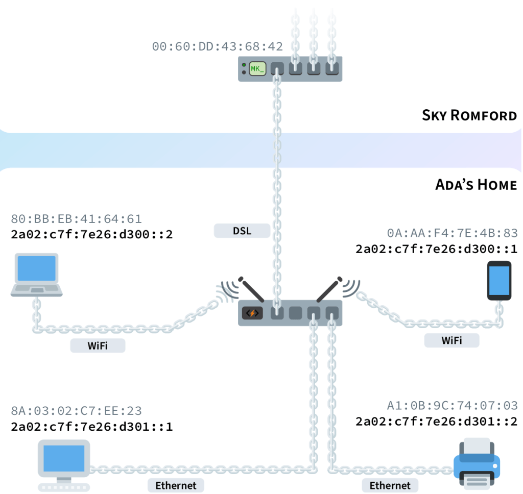
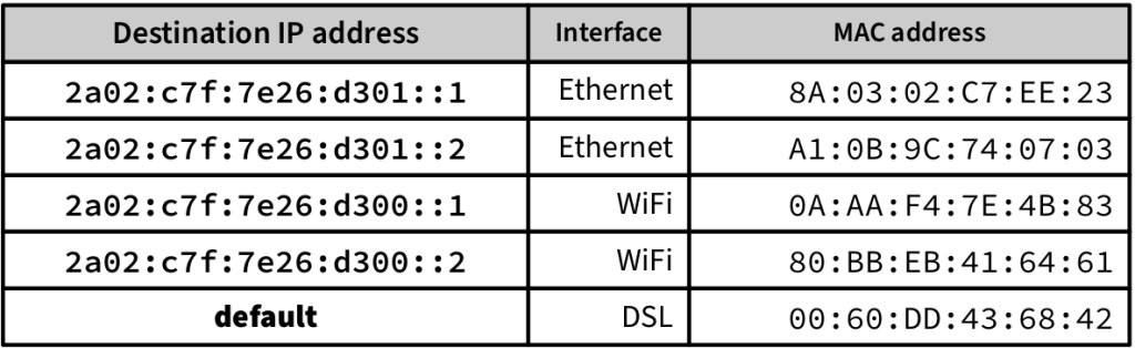
If the router receives a packet whose destination IP address doesn’t match any row in the table, the packet is forwarded through to the default route. For Ada’s router, routing is simple: a packet is either directly delivered to a computer in her home or forwarded to Sky Romford, her ISP.
Routing is more complicated for the ISP’s router. In addition to its peering and transit links, it receives packets from many different customers. For simplicity, let’s suppose Sky Romford’s router only serves two customers and has two peering links: one to the Sky router in Milton Keynes, and the other to Oxford University. Finally, let’s imagine it has a transit link with a larger telecom company:
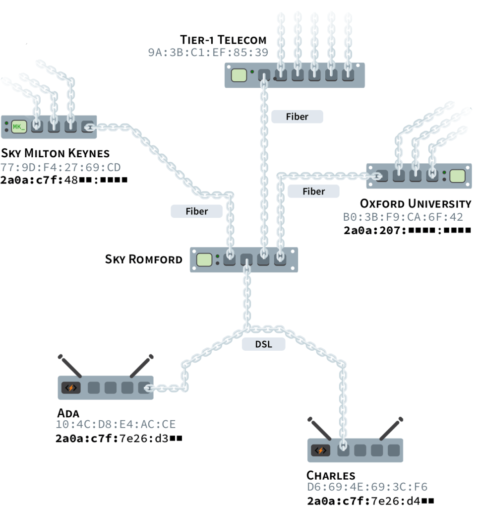
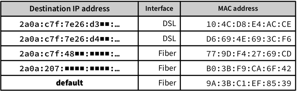
This is where the IP addressing hierarchy comes in handy. In the forwarding table of fig. 1.24, IP addresses are grouped according to their routing prefix. This works because all IP addresses starting with 2a0a:207 are from computers in Oxford University, and all IP addresses starting with 2a02:c7f:48 are from computers serviced by Sky in Milton Keynes.
Internet Exchange Points
In order to increase capacity and speed, network administrators often set up peering links with as many other organizations as possible. The cheapest way to do this is through places called Internet Exchange Points, or IXPs. Organizations join an IXP by wiring their routers to the IXP building. Every participating organization can then establish individual peering links with other organizations connected to the building.11
In fig. 1.23, only two peering links were shown for clarity’s sake. A typical ISP actually has scores of peering links per IXP they’re wired to. In addition, it’s common in big cities for Internet corporations like Netflix and Google to establish peering links directly with ISPs, allowing them shorter and faster connections to many of their customers.
Internet Backbone
ISPs and other telecom companies typically expand their interconnections as much as possible by establishing peering links wherever they can. However, in order to reach networks they cannot peer with, they have to buy transit from other operators.
There is a handful of companies in the world that don’t pay anyone for transit. These companies operate huge networks that all peer with each other, allowing regional ISPs to be interconnected globally. These huge networks are called Tier-1 networks, and they form the backbone of the Internet. Some Tier-1 networks are operated by AT&T, Verizon, and Lumen.12
Dynamic Routing
Large telecom companies must maintain connectivity even if some of their transit or peering links break down. This means that they can’t rely on a single link for each routing prefix in their table of addresses. In fact, they have dynamic routers that map out how other networks are interconnected in order to choose which routes to prioritize in their tables.
Dynamic routers periodically exchange information with other dynamic routers they’re linked to. They tell each other which network prefixes are reachable through each of their links. This allows them to determine how many hops away each link is from every routing prefix and where these hops occur. Dynamic routers can then determine the best route to each prefix based on metrics like distance and speed.13
With this information, dynamic routers build a table that covers all routing prefixes. For each prefix, the table indicates which next hop is on the best route to the final destination. When a link is established or a link goes down, dynamic routers inform their peers. As the news spreads, all of them update their tables to keep forwarding packets towards the best routes.
There is no central entity coordinating the exchange of this information: routers share link details with their peers freely and voluntarily. Consequently, routing problems often emerge.
Routing Loop
Misconfigured routers can provoke errors. Most notably, bugged tables of addresses can send a packet back a few hops, and it gets caught in an endless cycle of doom:
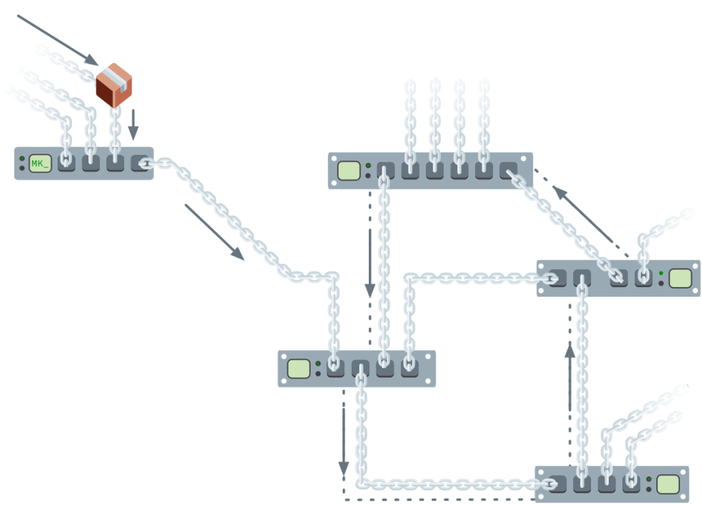
If the tables aren’t corrected, more packets with the same intended destination will be endlessly forwarded in circles. Too many packets can even saturate and clog the links. This is known as a routing loop problem. Fortunately, the Internet Protocol provides a way to identify the issue when it occurs.
HOP LIMIT — To interrupt perpetual routing loops, all IP packets carry a hop limit between 0 and 255. It indicates the number of times the packet can be forwarded by routers. Typically, packets are created with a hop limit of 64. Whenever a router forwards a packet, it reduces the hop limit by one:
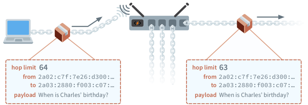
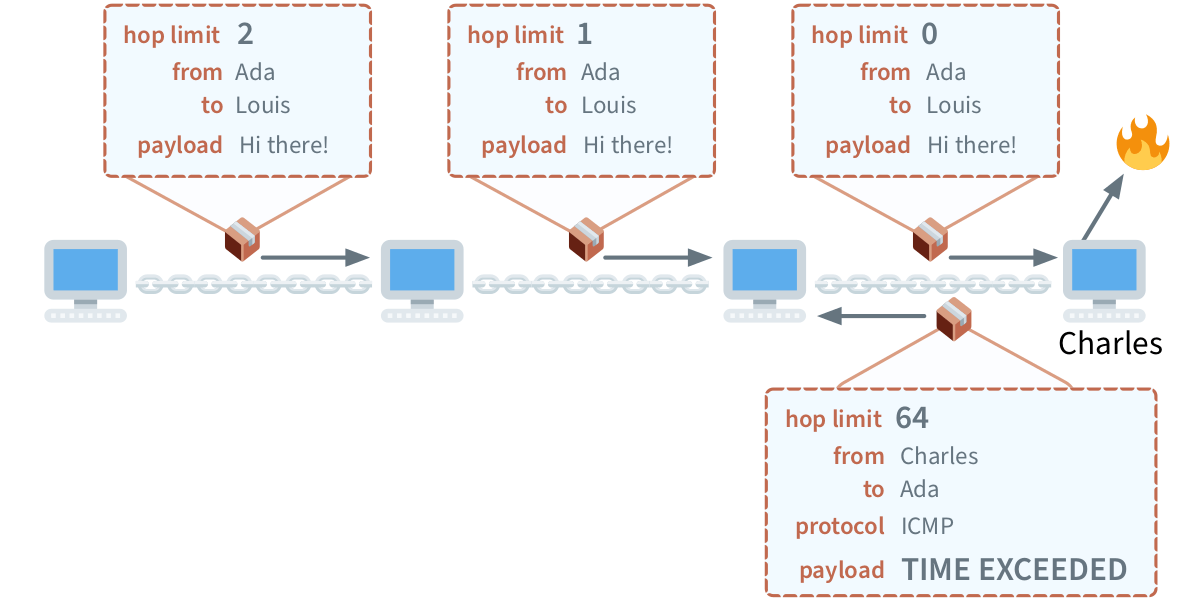
If a packet is going around in circles, its hop limit will eventually reach zero. If a router receives an IP packet with a hop limit of zero, it can be discarded. An IP packet containing an error message should then be transmitted back to the sender by the last router, stating that the packet could not be delivered because its hop limit was reached.
Feedback through such error messages helps network administrators fix critical bugs, and routing loops are not the only ones. In fact, the Internet Protocol covers how a variety of routing problems should be dealt with.
Diagnostics
Routers discard IP packets that they are unable to handle. When this happens, they send an informational message about the incident to the packet’s sender. The Internet Protocol defines how routers must format such messages, ensuring they can be understood by any computer. These rules are a subset of the Internet Protocol called the Internet Control Message Protocol (ICMP).
ICMP assigns error codes to the most common routing problems. To report a problem, a router sends an IP packet containing the error code as the message body, formatted according to ICMP rules. Let’s see some common problems that can be reported using ICMP, starting with the routing loop problem.
TIME EXCEEDED — If a router receives an IP packet with a hop limit of zero, its travel time is up. The packet either got stuck on a routing loop, or it was granted an insufficient hop limit by the sender.
In such cases, an ICMP message with a time exceeded error code is sent back. The ICMP message includes the first bytes of the discarded packet to allow the original sender to know which packet didn’t make it to its destination.
Notice that the IP packet Charles sends back in fig. 1.27 includes a protocol field. It’s a two-digit hex number identifying how the packet’s payload should be interpreted. The latest version of ICMP was assigned the protocol number 0x3A. All IP packets must include a protocol number. In the next section, we’ll learn more about this. For now, let’s explore other common routing problems.
DESTINATION UNREACHABLE — Sometimes, a router has nowhere to send a packet. This can happen for many different reasons, for example if the IP address isn’t in the router’s table of addresses, and the table doesn’t propose a default next hop. Sometimes, the next hop happens to be offline.
When the router doesn’t know where to forward the packet, it returns an ICMP message with the destination unreachable error code, along with the first bytes of the discarded packet’s content.
PACKET TOO BIG — We’ve seen that link layer protocols limit the amount of data that can be sent in a single frame. Frames from different types of network links can carry payloads of different sizes.
The maximum number of payload bytes that can be carried in a single frame is called its Maximum Transmission Unit (MTU). Different link layer protocols have different MTU values. For Ethernet frames, the MTU is 1,500. For WiFi frames, it’s 2,305.
If a router receives a larger packet than what the next hop can handle, it can’t be forwarded as it stands. Instead, the router returns an ICMP message with the packet too big error code, the first bytes of the problematic packet, and the MTU of the next hop. The informed sender can then trim or split the original message into smaller packets before trying again.
PARAMETER PROBLEM — An IP packet contains a lot of extra information alongside its payload. We’ve seen it contains IP addresses, a hop limit, and a protocol number. It also includes a field indicating the size of the payload and another specifying the version of the Internet Protocol it respects. Additional fields are also there to help routers prioritize important packets.
All these fields must be ordered and formatted according to strict rules. When a router receives a packet that doesn’t conform to the protocol, it returns an ICMP message with the parameter problem error code and the location in the packet where the conflict was found. As usual, the ICMP message also contains a few bytes of the discarded packet for identification purposes.
INFORMATIONAL MESSAGES — Error reports are not the only messages ICMP defines to inspect and diagnose faulty computer networks. Most notably, the echo request and echo reply informational message pair is widely utilized. When a computer receives an ICMP echo request, it returns a packet containing an ICMP echo reply.
This is useful to test if a computer is online. There’s a program called ping that sends out an ICMP echo request message and measures how long it takes for the reply to reach you.14 Furthermore, by sending ICMP echo requests with different initial hop limits, you can trace the route packets follow to reach their destination.15
We’ve seen that computers on the Internet can exchange information—such as ICMP messages—in IP packet payloads. However, the true power of the Internet is unleashed when applications, not computers, start using IP packet payloads to send each other data. This requires extra information to be included in the IP packets so that a computer can handle multiple streams of data for the different applications it runs. This extra information is described by the transport layer, which includes the famous TCP and UDP protocols.
To keep learning about these protocols, check out our book, Computer Science Unleashed. The book will also teach you how famous Internet applications such as email and the Web works. And it explains how DNS and domain names function under the hood! Understanding these technologies is essential for being a well-rounded web developer. Besides the Internet, Computer Science Unleashed also covers other three groundbreaking technologies: data analysis, machine learning, and cryptography. And it also includes a bonus chapter explaining how to use regular expressions!
Come check out the book!
1 In day-to-day life, we almost always express numbers in decimal form, where each digit is one of ten characters: 0, 1, 2, 3, 4, 5, 6, 7, 8, 9. Computer scientists, on the other hand, like expressing numbers in hexadecimal form, where each digit can be one of sixteen characters: 0, 1, 2, 3, 4, 5, 6, 7, 8, 9, a, b, c, d, e, f. For more about number bases, see Appendix I.
2 You can look up who manufactured a device by entering the first six digits of its MAC address at http://code.energy/mac-lookup.
3 National Security Agency, a US government spying organization.
4 Encryption allows messages to look garbled to eavesdroppers.
5 If we encode one byte per character, a WiFi frame has room for about 500 words, enough to fill a page of text.
6 By “IP”, we mean its latest version, IPv6. A legacy version of the protocol, IPv4, is still used, despite being released in 1981. IPv4 can only support about 3 billion computers. IPv6, launched in 2012, can support a virtually unlimited number of computers. As of 2020, a third of the Internet’s computers use IPv6.
7 We’ll present IP addresses as defined in the latest version of IP. Legacy IPv4 addresses are still used. They are written as four groups of up to three digit decimal numbers, separated by dots, for example, 192.168.0.1.
8 It takes 128 zeros and ones to write the number. This means it’s a number between 0 and 340,282,366,920,938,463,463,374,607,431,768,211,456.
9 This information is public, you can look up the network location of any routing prefix. The practice is called IP geolocation, and it’s how websites guess the country and city you browse from.
10 We’ve included the fields of the WiFi frame which also exist in Ethernet frames. A WiFi frame has more fields, which were hidden for simplicity.
11 IXPs are extremely important for making the Internet well connected and cheap. This video explains why: http://code.energy/IXP.
12 For an idea of how colossal these networks are, Lumen alone manages and operates 750,000 miles of fiber optic cables. That’s more than enough cable to reach the moon, three times!
13 All five RIRs constantly disclose information on all routing prefixes they delegate. Dynamic routers closely track these announcements, so they can ensure their tables have a row for every existing routing prefix.
14 You can send ICMP packets here: http://code.energy/ping.
15 An explanation of how ICMP is used to trace the routes IP packets travel through can be found at http://code.energy/traceroute.